
 中文
When standard FR-4 boards cannot handle the thermal loads your application demands, a metal core PCB (MCPCB) becomes the engineering decision that determines whether your product survives in the field. This guide covers MCPCB materials, thermal design, manufacturing, and the specifications you need when sourcing from a metal core PCB manufacturer.
What Is a Metal Core PCB?
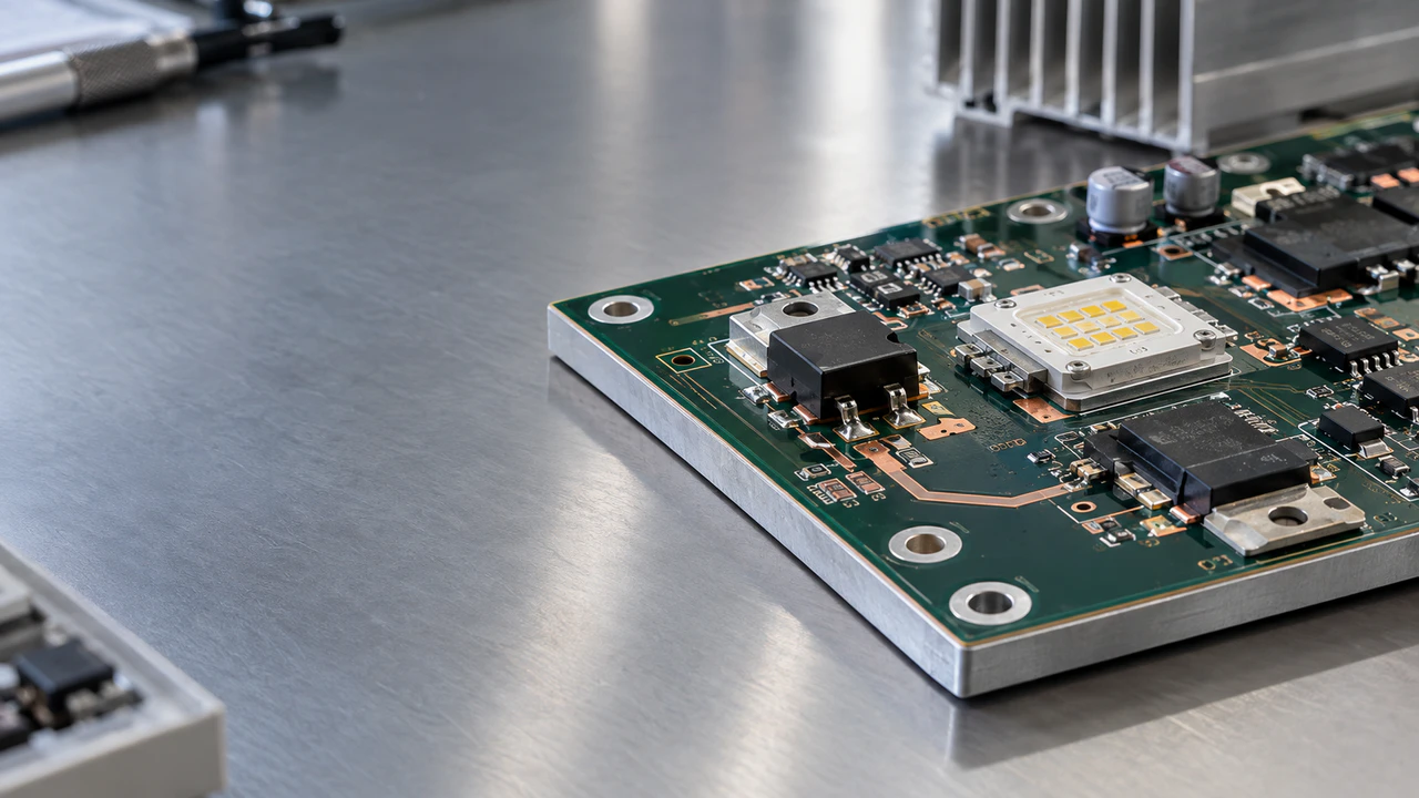
A metal core PCB (MCPCB) replaces the FR-4 fiberglass substrate with a metal base—typically aluminum or copper—that acts as an integrated heat spreader. You may also see these boards called IMS (Insulated Metal Substrate) PCBs, thermal PCBs, aluminum PCBs, or metal backed PCBs. These terms are often used interchangeably in PCB manufacturing, although their exact meanings can vary by supplier and construction. The fundamental structure is a copper circuit layer bonded through a thermally conductive dielectric to a metal core.
The technology dates back to the 1960s, but adoption expanded significantly with LED lighting in the 2010s. Today, MCPCBs are widely used in high-power LED products, automotive lighting, power converters, and any application where heat would degrade a conventional board.
The Thermal Path: Where Heat Actually Goes
Understanding MCPCB means understanding the heat path:
Component junction → Solder/thermal pad → Copper circuit → Dielectric layer → Metal core → Heatsink/chassis → Ambient
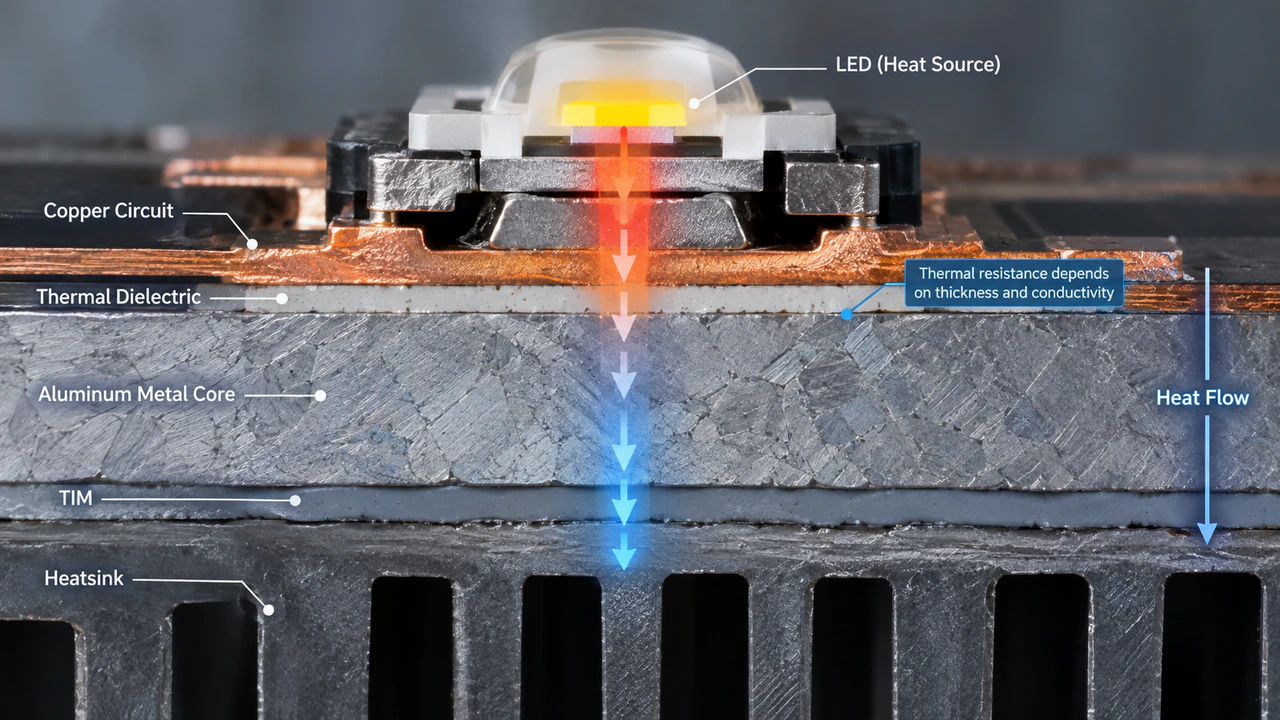
The metal core gets the attention, but the dielectric layer is where the engineering happens. Common aluminum alloys used for metal-core boards fall roughly in the 140–170 W/m·K range, depending on alloy and temper (MatWeb). Copper reaches approximately 385–400 W/m·K. But the dielectric layer—this thin dielectric layer, often around 50–150 μm in conventional constructions—must conduct heat efficiently while providing reliable electrical isolation between the circuit and metal core. Commercial MCPCB dielectric systems are available across a wide thermal-conductivity range, from around 1 W/m·K to several W/m·K, with some specialized materials reaching higher values.
A simplified thermal resistance model shows why this matters:
Rθ ≈ t / (k × A)
Thinner dielectric (t↓) and higher conductivity (k↑) both reduce thermal resistance. But thinner dielectric also reduces breakdown voltage. A 75 μm dielectric at 2.0 W/m·K gives roughly 0.4°C/W per cm². The same thickness at 1.0 W/m·K doubles to 0.8°C/W.
This is a simplified one-dimensional model. Real thermal analysis must include junction-to-case resistance, solder interface, copper spreading, TIM, heatsink, and convection. But it explains why dielectric selection—not metal core selection—is one of the key specification decisions in MCPCB design.
Aluminum Core vs Copper Core: A Practical Comparison
Aluminum is the most common metal-core material because it offers a practical balance of thermal performance, weight, cost, and machinability. The question of when to switch to copper is worth answering directly.
| Factor | Aluminum Core | Copper Core |
|---|---|---|
| Thermal conductivity | ~140–170 W/m·K (alloy dependent) | ~385–400 W/m·K |
| Weight | Light (2.7 g/cm³) | Heavy (8.9 g/cm³) |
| Cost relative to aluminum | Lower | Higher (varies with material, processing, and volume) |
| Machining | Straightforward | Demands specialized tooling |
| CTE | 23 ppm/°C | 17 ppm/°C |
| Best fit | LED, automotive, general power | High-power RF, dense LED arrays, extreme thermal |
Copper is not universally better. For a 5 W LED street-light design, aluminum with a suitable thermal dielectric may provide sufficient thermal performance at lower cost than a copper core, depending on the board area and cooling path. Copper has a lower CTE than aluminum and can reduce thermal-expansion mismatch in some high-reliability structures, depending on the package, solder system, and board construction. Copper earns its premium in very high heat flux or demanding thermal-cycling requirements.
Common aluminum alloys in MCPCB manufacturing:
- 5052 — 138 W/m·K, good formability, commonly available
- 6061 — 167 W/m·K (T6 temper), commonly available
- 3003 — 159 W/m·K, good corrosion resistance, used in harsh environments
MCPCB Stackup and Construction Options
Single-sided MCPCB is the most common configuration: copper on one side, dielectric, aluminum beneath. If your circuit fits on one layer—most LED designs do—this is your starting point. Short thermal path, lowest cost, simplest manufacturing.
Double-sided places copper on both faces of the metal core, separated by dielectric layers. This doubles your routing area but introduces a critical manufacturing challenge: for constructions where a plated through-hole passes through the conductive metal core, the PTH must be electrically isolated from it. Cost increases significantly compared to single-sided. At that price point, evaluate whether a copper-coin insert in FR-4 multilayer might serve better.
Multilayer MCPCB adds signal layers, power planes, and ground planes. But every additional dielectric and copper layer lengthens the thermal path from component to metal core. Layer count should be a joint decision between routing requirements and thermal path—not a reflex to add layers for routing density.
For projects that need both high layer count and thermal management, consider a hybrid approach: MCPCB for the power stage, Multilayer PCB for the control circuitry.
Thermoelectric separation / direct thermal path construction can reduce the thermal resistance of the local heat path by bypassing the conventional dielectric layer. Used in high-power LED arrays and COB designs where every degree matters.
The Via Problem: Why MCPCB Manufacturing Is Harder Than It Looks
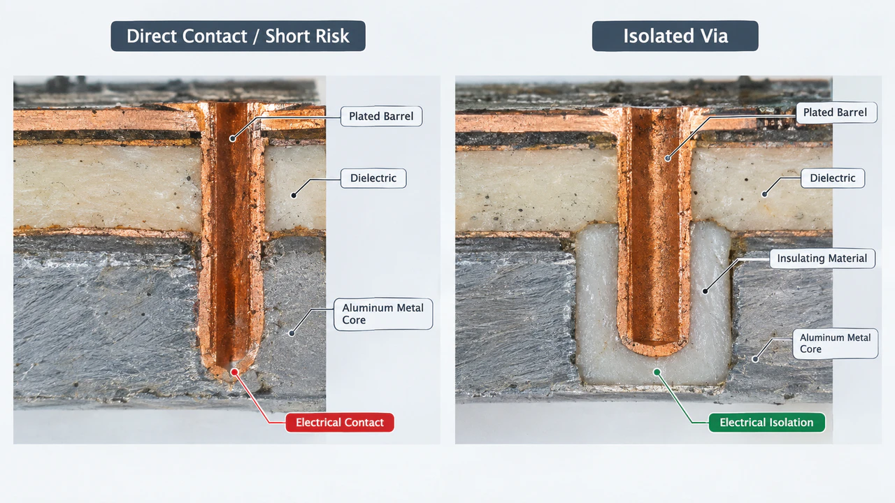
In a standard FR-4 board, a plated through-hole via passes through non-conductive material. No problem. In an MCPCB, that same via may pass through a conductive metal core. If the plated barrel contacts the aluminum or copper, you have just created a short circuit.
Depending on the construction, manufacturers may use insulated-core-hole, resin-isolation, or other specialized via structures to prevent the plated barrel from contacting the metal core. One common method: the manufacturer pre-drills a larger hole in the metal core, fills it with insulating material, and then creates the plated via through that insulation. This requires precise alignment, careful material selection, and testing to verify the isolation holds under voltage stress.
If you are sourcing a double-sided or multilayer MCPCB, ask the manufacturer specifically: "What via isolation method do you use, and what breakdown voltage does the isolated via achieve?" If they cannot answer this clearly, they may not have experience with the construction you need.
Metal Core PCB Manufacturing Process
The MCPCB fabrication sequence differs from standard FR-4 at several critical steps:
- Engineering review — Gerber files, drill data, stackup, thermal requirements, and via construction are reviewed against manufacturability. This is where incompatible specifications get caught.
- Metal base preparation — The selected alloy (5052, 6061, etc.) is cut, cleaned, and surface-prepared. Metal machining introduces burr and edge-quality considerations that differ from conventional FR-4 fabrication.
- Dielectric lamination — Copper, thermal dielectric, and metal base are bonded under heat and pressure. This step determines thermal resistance, dielectric strength, and long-term adhesion. It is not interchangeable with FR-4 lamination—different materials, different parameters, different failure modes.
- Circuit imaging and etching — Standard photolithography, adjusted for thicker copper and metal substrate handling.
- Drilling and via isolation — The critical divergence from FR-4. Plated holes through the metal core require insulated construction. Non-plated mounting holes do not require plated-barrel isolation, although their mechanical and electrical clearances still need to be specified.
- Solder mask and surface finish — White solder mask is common in LED applications for optical reflectivity. Surface finish options: HASL, ENIG, OSP.
- Routing and V-cut — Metal core requires different tooling, speeds, and burr management than FR-4.
- Electrical testing — Continuity, isolation, and dielectric withstand (Hi-Pot) testing. For MCPCBs, the Hi-Pot test is especially important because it verifies the dielectric isolation between circuit and metal core.
Common Pitfalls When Sourcing MCPCBs
Specifying metal core conductivity instead of dielectric conductivity. Some suppliers quote the aluminum base conductivity as the board's thermal performance. The number that matters is the dielectric layer conductivity—typically 1.0–3.0 W/m·K. Always ask for the dielectric datasheet.
Ignoring the thermal interface after the board. The MCPCB spreads heat to its aluminum base, but that heat still needs to leave the board. If the contact between board and heatsink/chassis is poor, the MCPCB's thermal advantage is wasted. Specify flatness tolerances and thermal interface material requirements in your RFQ.
Assuming higher dielectric conductivity always means lower thermal resistance. A 3.0 W/m·K dielectric at 150 μm thickness can have higher thermal resistance than a 2.0 W/m·K dielectric at 75 μm. Thickness matters as much as conductivity. Evaluate the ratio, not just the W/m·K number.
Treating MCPCB as just "FR-4 with aluminum." The manufacturing process, DFM rules, via construction, and failure modes are all different. A manufacturer experienced in FR-4 but not MCPCB may produce boards that pass electrical testing but delaminate under thermal cycling.
Over-specifying layer count. More layers mean more routing but a longer thermal path. For most LED and power applications, single-sided MCPCB is the right answer. Move to double-sided or multilayer only when routing truly demands it.
MCPCB vs FR-4: Which Should You Use?
| Factor | FR-4 | Aluminum MCPCB |
|---|---|---|
| Thermal spreading | Limited through-thickness conductivity | Better heat spreading through metal base |
| Routing density | Excellent | Best for simpler/specialized constructions |
| Layer count | Broad range | Construction-dependent |
| Weight | Lower than copper-core | Higher than FR-4 |
| Cost | Lower baseline | Higher material/process cost |
| Thermal management | Often needs vias or additional cooling | Better suited to thermally demanding designs |
| Typical applications | General electronics, dense digital | LED, power, automotive and thermal applications |
When MCPCB Is NOT the Right Choice
MCPCB is not a universal upgrade. Consider alternatives when:
- Dense multilayer routing dominates the design — Conventional FR-4 multilayer or HDI PCB may offer a better cost-to-routing trade-off. While multilayer MCPCB constructions exist, each additional layer increases cost and lengthens the thermal path.
- Flexible form factors are required — Conventional metal-core boards are rigid constructions and are not suited to applications requiring PCB-level flexing. Consider Rigid-Flex PCB instead.
- High-frequency electrical performance is the primary concern — Specialized RF laminates may offer a more appropriate stackup unless the metal-core structure has been specifically engineered for the required impedance and loss characteristics. See RF & Microwave PCB for dedicated RF constructions.
MCPCB selection should be based on the complete thermal budget rather than a single power-density threshold.
Standards and Testing That Apply to MCPCB
The following IPC standards are relevant to MCPCB design, materials, and qualification. IPC (now part of Global Electronics Association) is the industry authority for interconnect standards.
- IPC-6012F — Performance and qualification specification for rigid printed boards, including metal core constructions. Acceptance criteria should be defined with the applicable IPC acceptability standard and customer requirements.
- IPC-A-600M — Acceptability of Printed Boards. Used with applicable performance specifications to define visually and dimensionally acceptable board conditions. Complements IPC-6012F for MCPCB acceptance evaluation.
- IPC-2221C — Generic printed board design requirements that can be applied alongside construction-specific requirements. Not an MCPCB-specific standard, but provides the foundational design framework.
- IPC-2152 — Standard for determining current carrying capacity in printed board design. Relevant when combining MCPCB with heavy copper for high-current power paths.
- IPC-TM-650 — Test methods manual. Includes relevant methods for dielectric breakdown and dielectric withstand testing. Method 2.4.54 specifically addresses thermal transmission properties of metal-based printed boards, requiring measurement of dielectric layer thickness and calculation of apparent thermal conductivity.
Testing should go beyond continuity and isolation. Thermal resistance validation, thermal cycling, and copper–dielectric–metal interface inspection catch delamination and voids that static electrical testing misses but that cause failures in the field.
How to Choose a Metal Core PCB Manufacturer
Use this checklist when evaluating suppliers:
| Specification | What to Ask the Manufacturer |
|---|---|
| Core material and alloys | "Which aluminum alloys (5052, 6061, 3003) and copper cores do you stock?" |
| Dielectric thermal conductivity | "What W/m·K grades do you offer? Can you provide the dielectric datasheet?" |
| Dielectric thickness and tolerance | "What thickness options? What is the tolerance and resulting breakdown voltage?" |
| Copper weight range | "What copper weights do you support—from 1 oz to 10 oz?" |
| Layer construction | "Single-sided, double-sided, and multilayer—which do you manufacture?" |
| Via isolation method | "How do you isolate plated through-holes from the metal core? What voltage does it withstand?" |
| Surface finish options | "HASL, ENIG, OSP, and any specialty finishes?" |
| Testing | "Do you perform Hi-Pot testing? What voltage? Do you offer thermal cycling?" |
| Certifications | "UL, ISO 9001, IPC Class 2/3, IATF 16949?" |
| DFM support | "Do you review thermal requirements before quoting, or just accept Gerber files?" |
A supplier that questions your dielectric choice, checks your thermal path, and flags via isolation issues before production is worth more than the cheapest quote.
JetH PCB: Metal Core PCB Manufacturing Capabilities
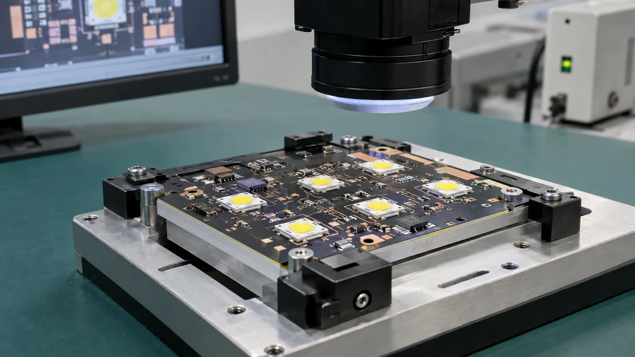
JetH PCB manufactures aluminum PCBs with the following MCPCB capability parameters:
| Parameter | Standard Range | Advanced |
|---|---|---|
| Board thickness | 0.3–3.0 mm | 0.2–5.0 mm |
| Copper thickness | 1–4 oz | 0.5–10 oz |
| Min trace/space | 0.10 / 0.10 mm | 0.075 / 0.075 mm |
| Thermal dielectric conductivity* | 1.0–2.0 W/m·K | 3.0 W/m·K |
| Surface finish | HASL / ENIG / OSP | Electroplated silver / gold fingers |
*Final material selection and applicable thermal-conductivity value are confirmed during engineering review.
These ranges are listed by parameter, not as one guaranteed combination on a single board. Final capability depends on the selected stackup, material, board size, hole construction, finish, and drawing review.
JetH PCB supports single-sided and double-sided aluminum PCB constructions, including designs that require electrically isolated plated through-holes. Each project undergoes engineering review covering thermal path, via isolation, dielectric selection, and mechanical interface before quoting.
Combining MCPCB with Heavy Copper: Metal core solves heat spreading; heavy copper solves current carrying. For high-power, high-current designs, an aluminum-core board with 3 oz or 4 oz copper addresses both simultaneously. Explore Heavy Copper PCB capabilities for these combined requirements.
Applications
- LED Lighting — Street lights, automotive headlights, architectural illumination, downlights. MCPCBs are widely used for LED lighting products where thermal management is a primary design concern.
- Automotive Electronics — Lighting systems, power converters, motor controllers in harsh thermal environments.
- Power Electronics — Switching regulators, DC-DC converters, motor drivers where MOSFETs and IGBTs dissipate significant heat.
- Industrial Control — Motor drives, solid-state relays, factory automation power modules.
- RF and Microwave — Selected high-power RF applications using copper-core MCPCBs for superior thermal performance.
- Solar and Renewable Energy — Power conditioning equipment, high-current interfaces, and thermally demanding energy-storage electronics.
FAQ
Does a higher W/m·K dielectric guarantee a cooler component?
No. Dielectric thickness, heat-transfer area, and the contact from aluminum base to the cooling structure all contribute. A 2.0 W/m·K dielectric at 75 μm can outperform a 3.0 W/m·K dielectric at 150 μm. Evaluate the thermal resistance, not just the conductivity rating.
Can I use heavy copper on a metal core PCB?
Yes. MCPCB handles heat spreading; heavy copper handles current density. They address different problems and combine well. Current carrying capacity depends on trace width, copper geometry, allowable temperature rise, and cooling—refer to IPC-2152 for conductor sizing. An aluminum-core board with 4 oz copper is relevant for power electronics and energy storage applications.
Why does my double-sided MCPCB cost so much more than single-sided?
The cost increase comes from via isolation construction—each plated hole through the metal core requires insulated construction to prevent shorting—and from the additional lamination cycle. The construction is fundamentally different from double-sided FR-4.
What should I send for an MCPCB quotation?
Gerber files, drill data, fabrication drawing, and quantity. Also include: intended thermal interface, any mandatory isolation test voltage, critical mechanical dimensions, and component heat output if known. If the dielectric grade is undecided, tell the manufacturer your thermal requirements and let them recommend a material.
Request a Metal Core PCB Quote
JetH PCB reviews every aluminum PCB project for thermal path, via construction, dielectric selection, and mechanical interface before confirming a manufacturing route. Send your Gerber files and thermal requirements—our engineering team responds within 24 hours with DFM feedback and a detailed quotation.
Request an Aluminum PCB Quote | Upload PCB File | Talk to a JetH PCB Engineer