Open Nav


Ask for Tech Support

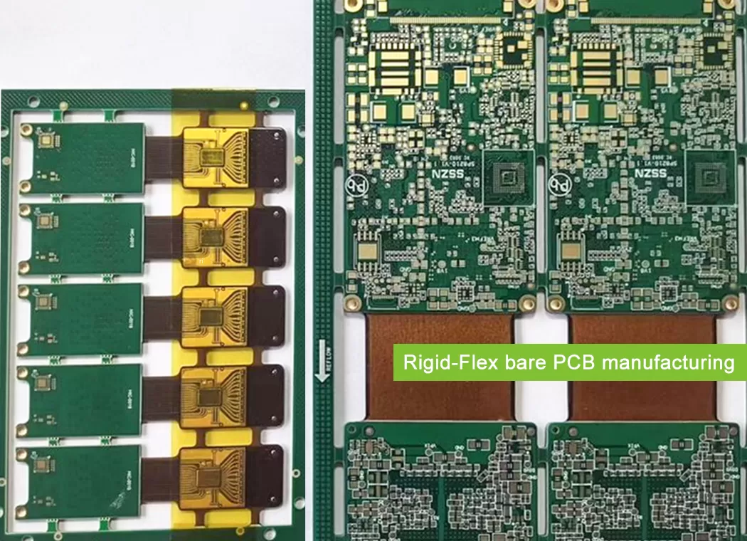
JetH Pro PCB Fab manufactures rigid flex PCBs for products where electrical routing and mechanical packaging must work as one system. Compact enclosures, folded assemblies, multiple rigid islands and controlled-flex interconnects are all within our engineering scope.
Send more than Gerber data when it is available. A regional stackup, bend definition, stiffener drawing or STEP model can expose manufacturing risks that ordinary PCB artwork cannot show.
Capability numbers establish the factory window. Final manufacturability still depends on how layer structure, flex thickness, copper, vias, bend conditions and production volume interact in the same design.
A 10-layer design may be easier to manufacture than a 6-layer board if its flex structure and transition geometry are better controlled. Layer count alone is not an engineering decision.
Outside one of the published limits? Send the stackup. We evaluate the combination before deciding whether the project can be released to production.
Before production release, our engineers compare the fabrication package with the actual rigid-flex construction and mechanical requirements.
Expand the questions below to see the areas that most often affect manufacturability.
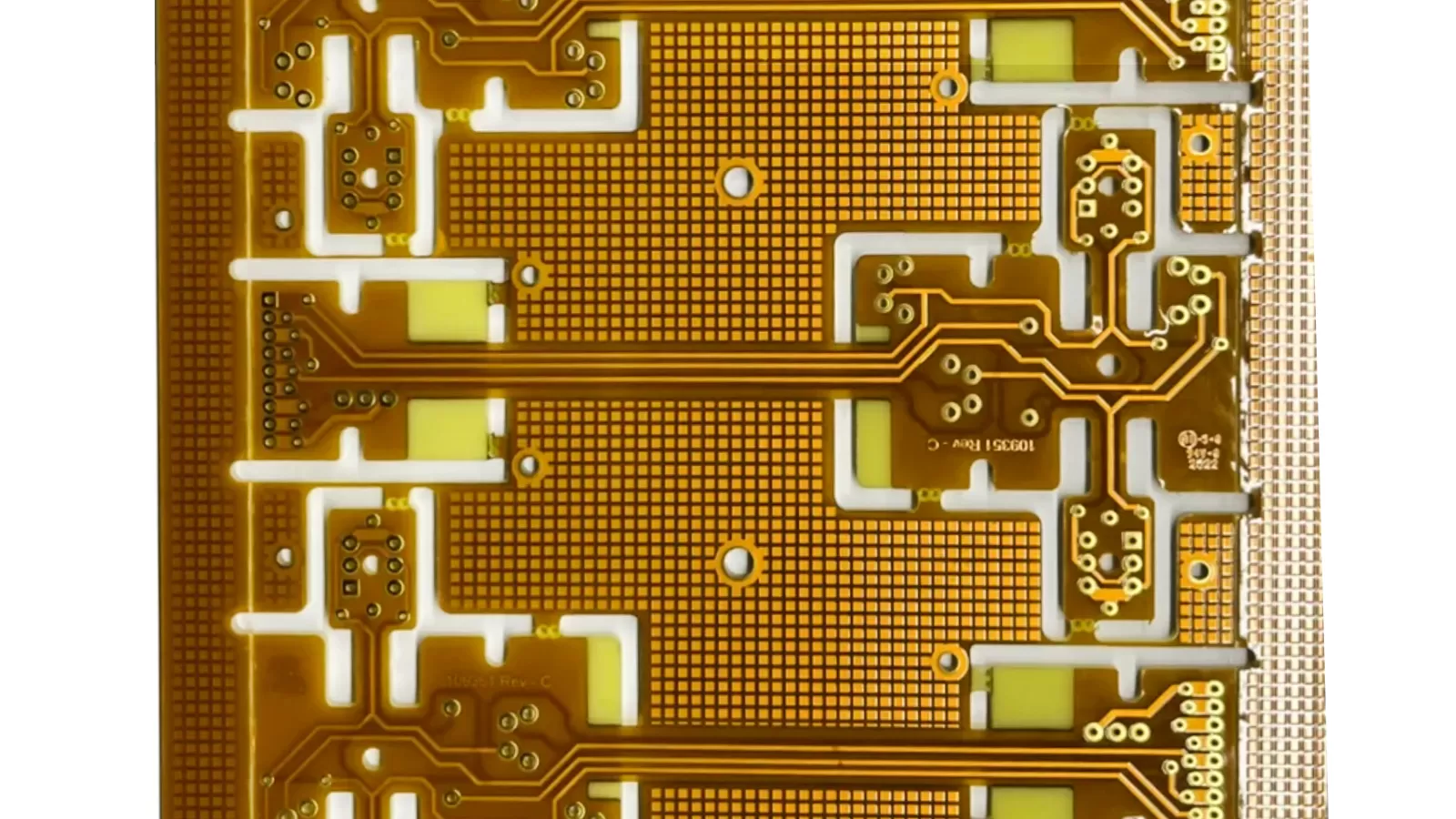
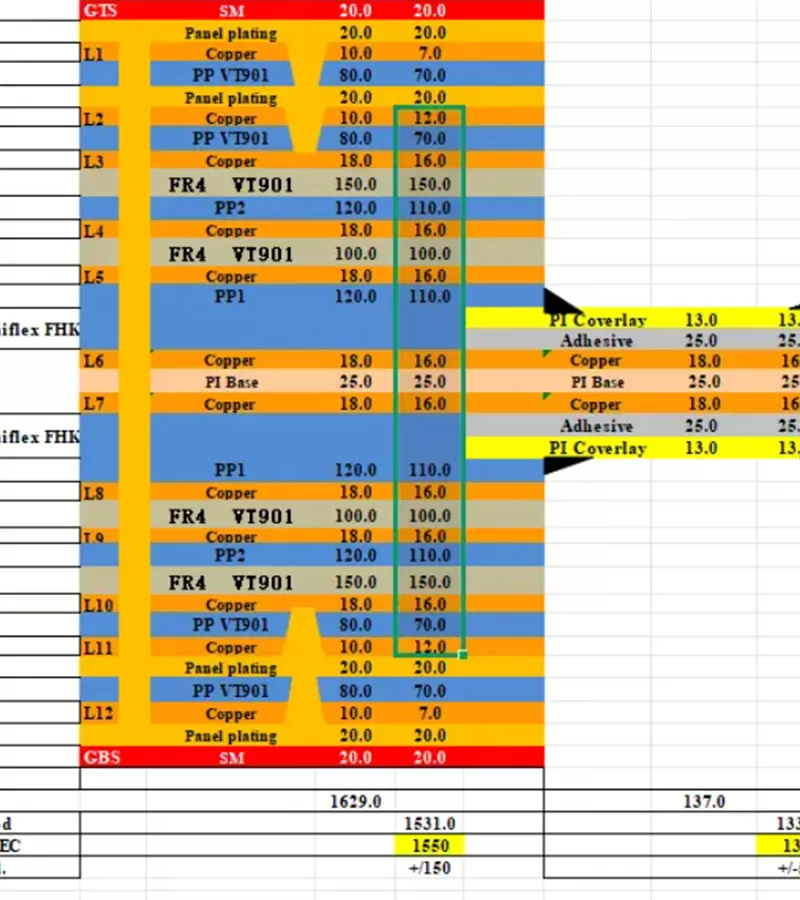
First we establish which copper and dielectric layers continue through each rigid and flexible region. Only then does it make sense to evaluate copper weight, polyimide, adhesive systems, coverlay, stiffeners, finished thickness and via construction.
Controlled impedance is reviewed against the regional structure rather than treated as one uniform board stackup.
Bend radius is only one variable.
Flex thickness, copper-layer count, trace orientation, copper distribution, bend direction and expected movement all affect the design. A one-time installation fold is not reviewed the same way as a section expected to flex repeatedly in service.
When the expected mechanical condition is unclear, that becomes an engineering question before it becomes a factory assumption.
This is where stiffness changes quickly, so features that are electrically acceptable can become mechanically vulnerable.
Vias near the transition, abrupt copper-width changes, poorly positioned coverlay edges, stiffener boundaries and unsupported loads all deserve closer attention. Ordinary PCB electrical checks may never flag them.
Not every project requires a STEP model, but mechanical data becomes valuable when enclosure geometry, connector insertion, component weight, mounting or folding creates load on the flex area.
A flat fabrication file cannot show us how the assembly behaves after installation. If that installed state matters, send it.
We don't simply return the design with an unexplained “NG” note.
The affected feature is identified, the manufacturing concern is explained, and a practical adjustment is suggested where one is available. If a requirement cannot change, we discuss the limitation before tooling or production release.
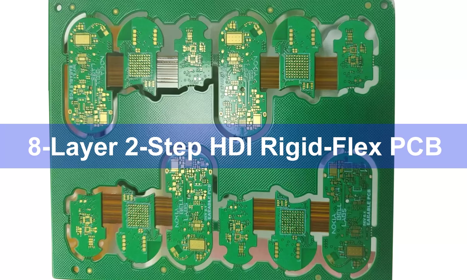
Components, connectors, dense routing and mechanical fastening usually sit here. The rigid region is often straightforward; its interaction with the flexible section is where additional engineering begins.
Flex layers carry the interconnect through folds or moving sections. Copper distribution, thickness and trace geometry become part of the mechanical design, not just the electrical layout.
Stiffeners support connectors, contacts or local mechanical loads. Coverlay openings and overlap dimensions need to work with the pad design, bend area and transition boundaries.
Fabrication data should identify where rigid materials stop, which conductive layers continue through the flex section and how total thickness changes by region.
A one-time installation fold and a dynamic flex section can require completely different engineering assumptions, even when both boards appear similar in the flat state.
A successful prototype should answer more than “does the circuit work?” It should tell us whether the construction, dimensions, handling method and inspection plan are ready for the next build.
Learn more about JetH Pro PCB Fab and our PCB Quality Management .
Prototype is the right place to verify finished thickness, folded geometry, enclosure fit, electrical performance and test access while design changes are still manageable.
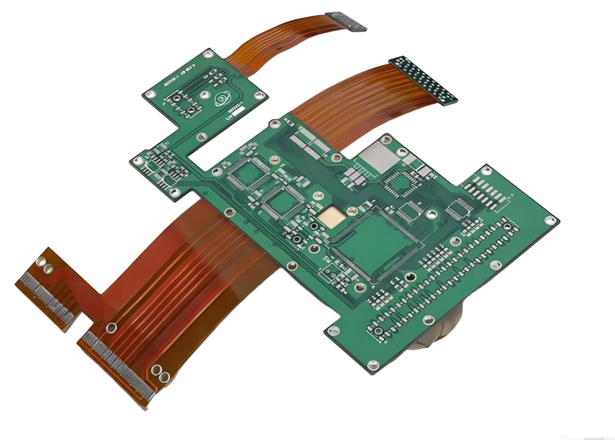
After validation, the focus changes. Materials, tooling, inspection criteria, testing, packaging and engineering-change control need to remain stable from one production lot to the next.
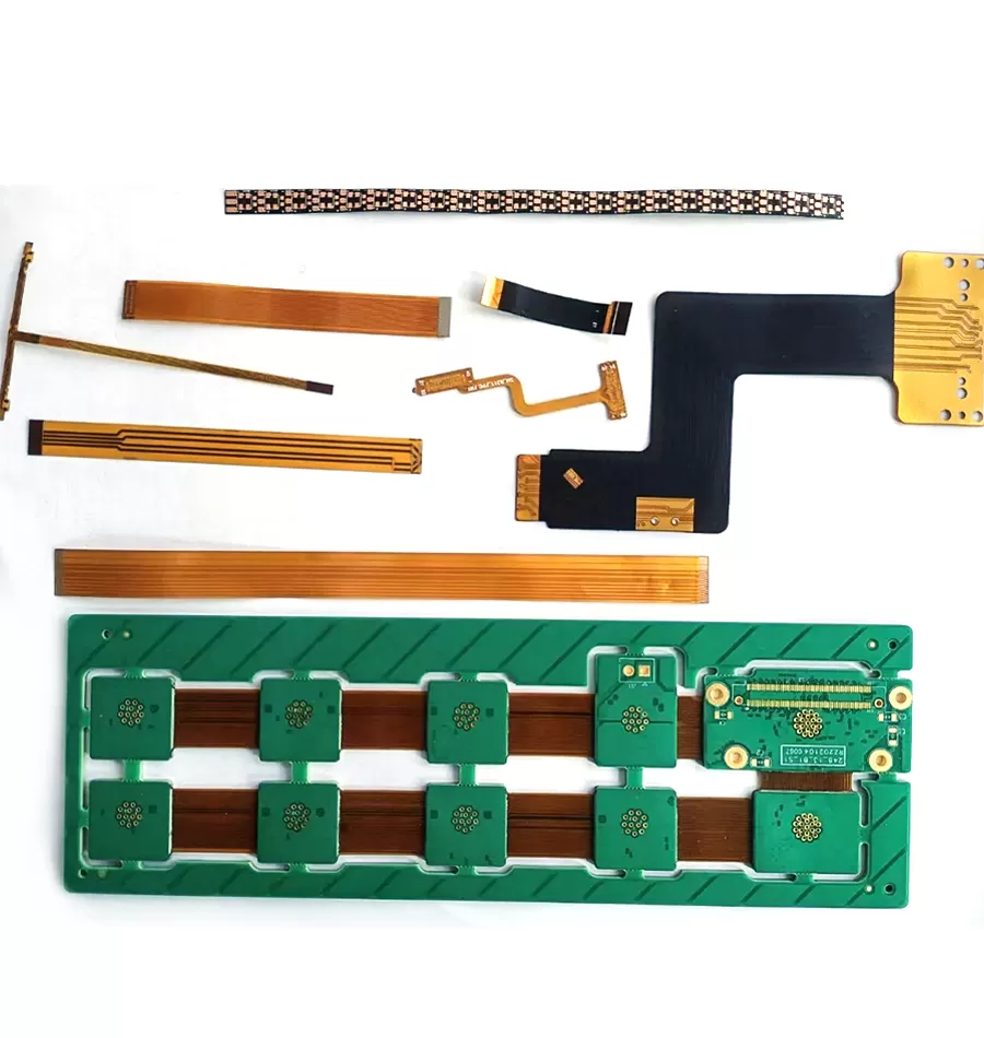
Unsupported flex changes how the assembly behaves on the line. Carrier support, SMT processing, folding, fixtures, connector loading and functional testing may all become part of the process plan.
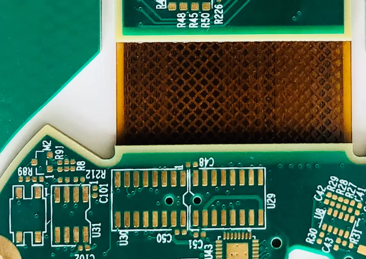
Electrical continuity is necessary, but it does not prove that every internal feature was built correctly. Registration, material construction, transition areas and critical process results also have to be verified.
You do not need a perfectly finished design before starting a manufacturing discussion.
Send what is already defined and identify what cannot change. JetH Pro PCB Fab can then separate fixed requirements from stackup, material or process variables that still have room for optimization.
Gerber or ODB++ data is a starting point. For a meaningful engineering review, include the fabrication and mechanical information that defines how the board is expected to be built and used.
Yes. Early contact is often useful when stackup, material selection, bend geometry or production volume are still being defined.
Tell us which requirements are fixed. We can then state the assumptions used for feasibility and quotation instead of pretending that missing information has already been decided.
Price follows the construction. Board dimensions and quantity matter, but rigid-flex cost can change substantially with materials, flex-layer structure, HDI features, testing requirements and the assembly scope.
Rigid-flex is most useful when mechanical packaging and electrical interconnection can no longer be treated as separate problems.
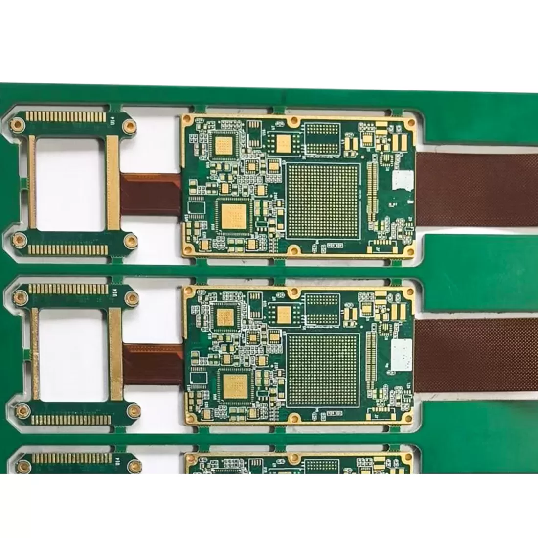
Rigid-flex can replace separate cable-and-connector interfaces, allowing the interconnect to fold into the available mechanical volume. This is useful where enclosure space is more restrictive than PCB area.
Compact medical electronics often require circuits to pass through narrow housings, curved assemblies or multiple mechanical planes. Rigid-flex allows the interconnect geometry to be designed around that physical package.
Equipment with multiple internal planes, moving assemblies or difficult connector access can benefit from combining structural PCB sections and flexible interconnects into one manufactured part.
In applications where packaging, weight, connector count and assembly complexity all matter, rigid-flex can support a more integrated interconnect architecture. The actual construction still needs to be matched to environmental and mechanical requirements.
Have final files? Send them.
Still working through stackup, bend radius or mechanical packaging? Send the current design anyway. JetH Pro PCB Fab can review the manufacturing variables before the project is locked into a construction that is expensive to change.
Our team will get back to you within 24 hours
 DFM & Design Review
 Technical Consultation
 Fast Response
 中文