

 中文
When evaluating an aluminium PCB board for LED lighting, start with the thermal requirements of the LED package and the complete fixture, rather than choosing a board by its thermal conductivity rating alone.
An aluminum printed circuit board — also called an aluminum metal-core PCB (MCPCB) — consists of copper circuitry, an electrically insulating thermal dielectric, and an aluminum base. It is widely used in LED street lights, downlights, and linear lighting, but it is not automatically the best choice for every LED design: the decision depends on the heat the LEDs generate, the required electrical isolation, the available cooling area, and how the PCB meets the fixture or heatsink. This guide covers the complete thermal path, the dielectric layer, copper and base thickness, board structure, and what to prepare before ordering.
Published by JetH PCB
1. Determine Whether an Aluminum PCB Is Necessary
The choice between an aluminum MCPCB and an FR-4 PCB is a thermal-budget decision: keep the LED junction temperature within the manufacturer's limits while meeting the electrical, mechanical, and cost requirements. Before selecting a substrate, establish the LED package and drive conditions, the heat each LED dissipates and its placement, the permitted junction temperature and package thermal resistance, the available heatsink area and ambient conditions, and the insulation and layout requirements.
Aluminum MCPCB vs. FR-4 PCB
| Selection factor | Aluminum MCPCB | FR-4 PCB |
|---|---|---|
| Thermal design | Metal base spreads heat through the thermal dielectric | Copper planes and thermal vias carry heat toward a heatsink |
| Circuit layout | Common single-sided structures offer less routing flexibility | Suits complex, multilayer layouts |
| Mechanical integration | Metal base supports a defined contact interface with the fixture | Stiffness, mounting geometry, and interface must be evaluated together |
| Insulation | Dielectric separates copper from the conductive metal base | Laminate insulates between conductive layers |
| Typical use | LED lighting and power electronics needing a metal substrate | Designs whose thermal needs are met with copper and vias |
An FR-4 design should not be ruled out just because the product contains LEDs. Cree LED's application note, Optimizing PCB Thermal Performance for XLamp LEDs, describes using metalized thermal vias beneath suitable LED thermal pads so that FR-4 can replace a metal-core board in certain designs, with potential system-level savings in board and heatsink cost. The same note states this technique is not recommended for XLamp LEDs consuming more than 5 W — a limit that applies to that technique and those products, not a universal cutoff between FR-4 and aluminum. The actual decision must follow the LED package requirements, board construction, and thermal analysis.
2. Evaluate the Complete Thermal Path
Heat travels from the LED junction through the package and board, across the mounting interface, and into a cooling structure that dissipates it to the environment. The two common constructions move that heat in different ways.
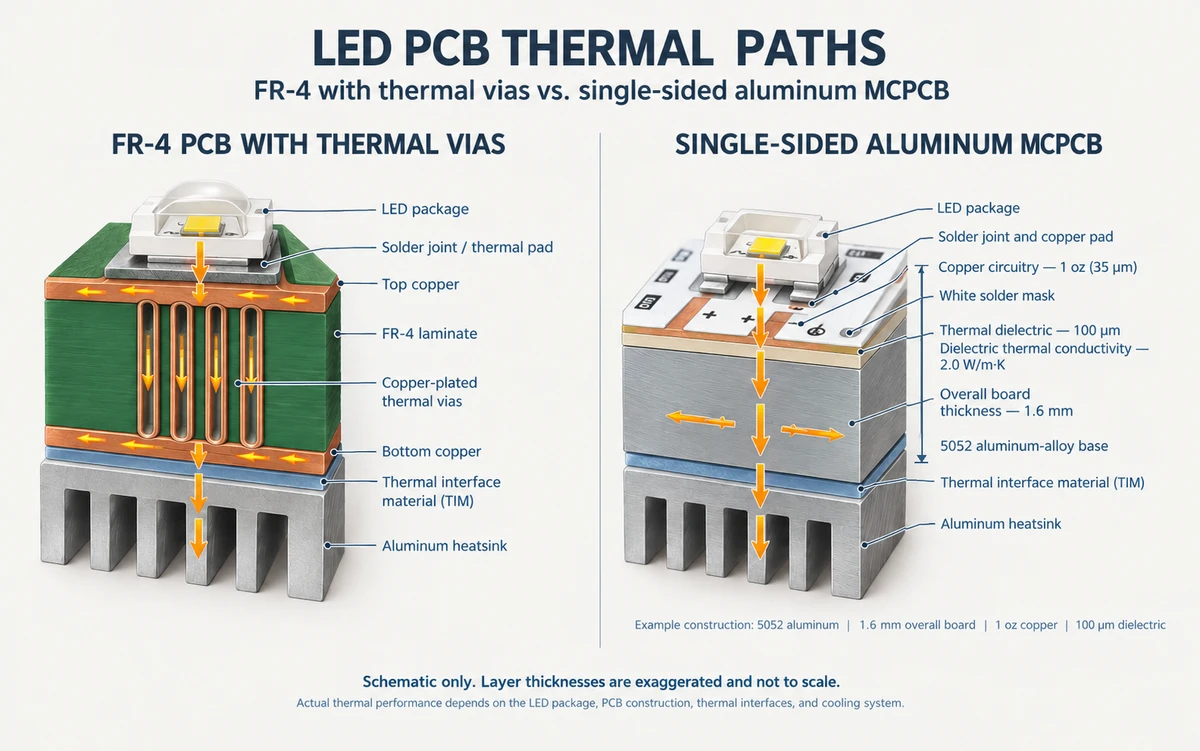
For a simplified design in which this is the dominant path:
Tj ≈ Ta + Qheat × (RθJS + RPCB + RTIM + Rheatsink)
Where Tj is the junction temperature, Ta the ambient temperature, Qheat the heat dissipated by the LED, RθJS the package's junction-to-solder-point thermal resistance, RPCB the resistance through the PCB, RTIM the interface resistance, and Rheatsink the heatsink resistance to ambient. Use the reference point the LED datasheet actually specifies — some use junction-to-case instead, and values with different reference points must not be mixed in one chain.
For a single LED with one dominant heat-flow path, this equation gives a first-order estimate. Here, Qheat is the heat dissipation rate in watts, and each thermal resistance is expressed in K/W. The thermal-resistance definition and power term must match those used in the LED datasheet: electrical input power is not automatically heat dissipation, because part of the input becomes light. RPCB represents the thermal resistance from the LED's solder-point reference through the PCB to its mounting interface, so the chain stays aligned at the same reference point. For a multi-LED assembly, account for the shared heatsink, total heat load, and thermal coupling between LEDs rather than applying the equation independently to every device.
Why the PCB-to-heatsink interface matters
The aluminum base spreads heat, but it cannot guarantee that the finished assembly dissipates it. Poor contact, air gaps, an unsuitable thermal interface material (TIM), or insufficient mounting pressure can dominate the total resistance. When evaluating an LED street light PCB or any lighting board, check mating-surface flatness, available contact area, TIM type and thickness, mounting-hole positions and pressure, and the heatsink's real-world capacity.
Junction temperature affects light output and service life: high junction temperatures can reduce both. It is normally determined by a defined measurement or estimation method rather than measured directly. Use the LED manufacturer's data and validation methods; see ams OSRAM's Package-related thermal resistance of LEDs.
3. How to Choose the Thermal Dielectric Layer
The thermal dielectric must electrically isolate the copper from the conductive aluminum base while allowing heat to pass through. Three properties need to be evaluated together:
- Thermal conductivity: Expressed in W/m·K, this describes the material's ability to conduct heat under specified test conditions. A higher value can reduce thermal resistance when other relevant conditions are comparable, but it does not independently determine the LED junction temperature.
- Dielectric thickness: A thinner layer can reduce through-plane thermal resistance. The finished construction must still meet the required dielectric withstand voltage — confirm insulation performance from material specifications and applicable test conditions, not from thickness alone.
- Electrical insulation: Confirm the required test voltage, test method, test points, and acceptance criteria. Similar thermal conductivity ratings do not imply equivalent electrical insulation performance.
For a single homogeneous layer under one-dimensional, steady-state heat flow, its through-plane resistance is Rth = t / (k × A), where t is layer thickness, k thermal conductivity, and A the effective area normal to the flow. This assumes constant k, uniform flux over A, and negligible contact resistance — it describes one layer, not the whole LED module, and it shows why conductivity alone is insufficient: thickness and effective area matter equally, and heat spreads laterally before crossing the layer, so real geometry may need fuller analysis.
Compare Thermal Conductivity Values Using the Same Definition
Material datasheets may report a thermal conductivity for the complete product and a different value for the thermal dielectric layer alone, measured by different methods, so identify the property and its test method before comparing materials. Where available, area-normalized thermal impedance in °C·cm²/W gives another way to compare dielectric constructions at specified thicknesses, provided the test methods and specimen configurations are comparable. Thermal conductivity and thermal impedance describe different aspects of performance and are best read together with the required electrical insulation.
JetH PCB's published aluminum PCB manufacturing reference lists dielectric-layer thermal conductivity across a 1.0–2.0 W/m·K standard range and a 3.0 W/m·K advanced reference. These are material-level capability references, listed by parameter and confirmed for each project against the LED package, thermal path, and isolation requirements. The sample in Section 4 uses a 100 μm dielectric rated at 2.0 W/m·K, selected to match that project's thermal and electrical design.
4. Choose Copper Thickness, Aluminum Base Thickness, and Board Structure
Copper thickness and layout. Copper carries current and spreads heat laterally (1 oz ≈ 35 μm). The right weight depends on current, trace width, copper geometry, and temperature-rise requirements; heavier copper also affects fine-line fabrication, etching, pad geometry, soldering, and cost. Do not select copper thickness by LED wattage alone.
Aluminum base thickness. The base spreads heat and provides mechanical support; choose its thickness against board dimensions, mounting arrangement, fixture space, stiffness, and contact with the cooling structure. A thicker base does not automatically lower the junction temperature — the dielectric, interface, mounting contact, or heatsink may dominate the total resistance.
Single-sided, double-sided, and multilayer structures. Single-sided construction is the common starting point when the circuit fits on one side. Double-sided aluminum PCBs are possible when routing or components are needed on both faces, but the aluminum base is electrically conductive: where plated through-holes (PTH) are used, the isolation construction must prevent the plated barrel from contacting the conductive aluminum — whether through a clearance, resin-based isolation, an insulating sleeve, or another qualified structure — and each proposed construction must pass a manufacturing-feasibility review against hole location, connection, isolation distance, and required testing. Do not transfer FR-4 hole-design assumptions to a metal-core board. Multilayer metal-core structures exist, but their feasibility and cost depend on the stack-up — confirm the construction with the manufacturer before finalizing the layout.
Example: A Single-Sided Aluminum MCPCB for LED Lighting
A representative JetH PCB sample shows how material selection and board construction come together in a manufacturing specification. The board is a single-sided aluminum MCPCB built on an insulated metal substrate (IMS), using a 5052 aluminum-alloy base, 1 oz copper, and a 100 μm thermal dielectric rated at 2.0 W/m·K.
| Parameter | Example specification |
|---|---|
| Board type | Single-sided aluminum MCPCB |
| Substrate | Insulated metal substrate (IMS) |
| Aluminum base material | 5052 aluminum alloy |
| Board thickness | Confirmed per project for the required mechanical and thermal design |
| Copper thickness | 1 oz (approximately 35 μm) |
| Thermal dielectric thickness | 100 μm |
| Dielectric thermal conductivity | 2.0 W/m·K |
| Solder mask | White |
| Silkscreen | Black |
| Surface finish | Lead-free HASL |
| Board-material flammability rating | UL 94 V-0, as specified for this material |
| Fabrication | V-cut panelization, routed board outline, drilled holes |
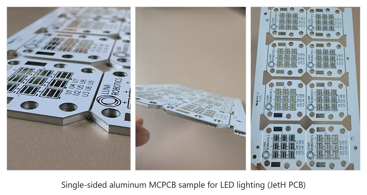
These specifications describe one production example. Copper thickness, dielectric properties, board thickness, and fabrication features are confirmed for each project against the LED package, thermal requirements, electrical isolation, and mounting conditions, so a lighting design can be built to its own thermal and mechanical targets. For projects needing different thermal or electrical characteristics, the proposed material and stack-up are confirmed with the PCB manufacturer before the design is finalized.
Thermal cycling. ams OSRAM's PCB technologies for LED applications notes that CTE differences can stress solder joints when ceramic-based LEDs are mounted on an insulated metal substrate; copper-core substrates, with a lower CTE than aluminum, may be worth evaluating — alongside weight, cost, and the rest of the cooling system.
5. How to Choose an Aluminum PCB for Different LED Applications
The right construction depends on the LED layout, heat distribution, board geometry, and how the board integrates into the fixture:
| LED application | Main selection considerations | Details to confirm |
|---|---|---|
| LED street lights | Distributed heat sources, board dimensions, heatsink integration | LED layout, mounting holes, board outline, contact area, fixture interface |
| High-bay and floodlights | High heat loads and concentrated hotspots | Heat distribution, available cooling area, dielectric requirements, heatsink design |
| LED bulbs and downlights | Compact geometry, limited cooling space | Board outline, component spacing, fixture contact, assembly clearance |
| Linear lighting and backlighting | Board length, LED spacing, temperature uniformity | Board dimensions, copper layout, mounting conditions, thermal distribution |
| Automotive, stage, and specialty modules | Application-specific layouts and mechanical constraints | Component placement, cutouts, exposed-copper features, mounting interface, qualification |
| COB LED modules | High local heat flux, package-specific thermal needs | Package thermal data, contact geometry, dielectric construction, cooling arrangement |
Selecting an LED street light PCB
For an LED street light PCB, evaluate the distribution of LEDs across the board rather than the total electrical power: hotspot locations, available aluminum base area, and the contact surface between PCB and housing all shape the thermal design. Check the board outline, mounting holes, and fixture interface early, and remember that no fixed dielectric conductivity or aluminum thickness suits every street-light design.
Selecting an MCPCB for LED Bulbs and Downlights
For LED bulbs and downlights, available space constrains board shape and LED placement; evaluate component spacing, heat-spreading area, and how heat leaves the board into the fixture.
6. What Affects the Cost of an LED Aluminum PCB?
Cost follows the complete manufacturing specification. The main factors:
- Board material and dielectric grade: construction, thickness, and required electrical performance.
- Copper weight and circuit geometry: trace/space dimensions and the manufacturing requirements of the layout.
- Board dimensions and order quantity: panel utilization, prototypes, and repeat volume.
- Special structures: custom outlines, slots, double-sided connections, insulated plated through-holes.
- Surface finish and testing: selected finish plus any required electrical, dimensional, or reliability inspections.
Distinguish the PCB's unit price from the cost of the complete lighting system. An aluminum MCPCB may reduce the need for separate heat-spreading structures, but it does not guarantee a lower total system cost — that depends on the substrate, interface, heatsink, assembly, and production requirements.
7. What to Prepare Before Ordering an LED Aluminum PCB
A complete design brief lets the manufacturer evaluate feasibility and identify open engineering decisions before production:
- Fabrication: Gerber files, drill data, board outline, manufacturing drawings, and proposed stack-up if available; copper thickness, board thickness, surface finish, and special routing or hole requirements.
- Electrical and thermal: LED part numbers and datasheets, arrangement, drive conditions, thermal requirements, and maximum permitted junction temperature; required isolation, withstand-voltage tests, test points, and acceptance criteria.
- Product fit: Fixture or heatsink drawings, mounting-hole positions, critical dimensions, assembly clearances, and the surface contacting the PCB; any required TIM and other constraints on the thermal path.
- Order and inspection: Prototype quantity, expected repeat demand, selected finish, and required inspection or test records, including any reliability or environmental requirements.
You do not need to assign a precise dielectric conductivity or material number before the design is defined. If you are still evaluating options, state the required thermal performance, isolation conditions, and mounting arrangement — the manufacturer can then assess suitable materials and structures against those requirements.
Conclusion: Select the PCB for the Complete LED Thermal Design
Choosing an aluminum PCB for LED lighting starts with the LED package's thermal requirements and the complete path from junction to ambient. Compare aluminum MCPCB and FR-4 by the actual thermal budget rather than a wattage rule of thumb; select the dielectric on both thermal resistance and electrical isolation; and confirm the structure — including insulated PTH where needed — can be manufactured as designed. JetH PCB provides aluminum PCB manufacturing with project-specific engineering review; its published ranges are design-discussion references, not guaranteed combinations.