
 中文
An aluminum MCPCB is worth considering when board-level heat spreading is a priority, the routing fits a single-sided or otherwise limited-layer construction, and the board can make a defined thermal connection to the housing or heatsink. FR-4 is generally the more flexible starting point for dense or multilayer routing. If an FR-4 design with copper planes, thermal vias and a heatsink meets the component temperature target, compare the complete thermal solution (board, cooling hardware, mounting interface, space and cost) before changing substrates. This guide compares aluminum PCB vs FR-4 — and FR-4 vs aluminum PCB from the routing and cost side — on structure, thermal performance, routing, electrical isolation and manufacturing trade-offs.
Published by JetH PCB
What Is the Difference Between Aluminum PCB and FR-4?
The two substrates differ in how heat leaves the components and in how many routing layers you can build. Both follow from how each board is constructed.
Aluminum PCB Construction
A typical aluminum metal-core PCB (MCPCB) has three parts: a copper circuit layer, an electrically insulating thermal dielectric, and an aluminum base. The aluminum base spreads heat across the board and into the housing or heatsink. The dielectric between the copper and the aluminum deserves particular attention. It must electrically isolate the circuit from the conductive metal, and it often contributes a major share of the board-level through-thickness thermal resistance. Choosing an aluminum PCB material therefore means evaluating dielectric thickness, thermal conductivity and voltage rating together.
Aluminum boards are most often single-sided. Double-sided aluminum PCBs with insulated plated through-holes also exist, but they are specialty constructions that need review (covered below). For a look at what a manufacturer can build, see our custom aluminum PCB manufacturing page.
FR-4 PCB Construction
FR-4 is a flame-retardant grade of glass-reinforced epoxy laminate. Standard rigid boards stack copper layers and FR-4 dielectric, and connect them with plated through-holes and, where needed, blind, buried or laser-drilled microvias. That stack-up lets you give signals, power and ground their own layers, which is why FR-4 is the default for dense, multilayer designs. Heat moves mainly through copper: planes, pours, and thermal vias under hot components, then into an external heatsink or the enclosure. If your design needs a high layer count, controlled impedance or HDI, our multilayer PCB manufacturing page lists what is available.
Aluminum PCB vs FR-4: Key Differences
Use this table to see which constraints your design puts on each option. A "better" substrate depends on which row matters most for your product.
| Factor | Aluminum PCB | FR-4 PCB |
|---|---|---|
| Thermal design | The metal base helps spread heat laterally; heat transfer to the housing or heatsink depends on the dielectric layer and mounting interface. | Heat is carried by copper planes, thermal vias and an external heatsink or enclosure. |
| Routing complexity | Usually single-sided or a limited layer count. | Suited to multilayer routing and dense interconnects. |
| Via design | A plated hole through the aluminum base must be isolated from the metal, so it needs a purpose-built insulated structure. | Standard plated through-holes and multilayer interconnects are mature and widely available. |
| Electrical isolation | The copper circuit must be isolated from the conductive aluminum base. Check the required withstand voltage against the dielectric. | Layer-to-layer insulation comes from the laminate itself. |
| Manufacturing | Hole structure, dielectric specification and base processing all affect manufacturability. | Standard multilayer constructions offer a broader range of fabrication options. |
| Cost | Driven by dielectric grade, board thickness, special structures and quantity. | Standard designs usually have wide sourcing options. A demanding thermal design (heavy copper, dense via arrays, large heatsinks) also adds cost. |
| Typical fit | LED boards and some power electronics where board-level heat spreading matters. | Control boards, digital circuits and designs that need multilayer interconnects. |
Cost deserves a system view. Some designs trade a pricier substrate for a simpler cooling assembly, and others do the opposite: an FR-4 board with a dense thermal-via array and a large heatsink can cost more than its substrate price suggests. Compare the total solution, not the bare-board price alone.
Thermal Conductivity vs. Actual PCB Thermal Performance
If you search for "aluminum PCB thermal conductivity" or "high thermal conductivity PCB", you will find numbers in W/m·K. Treat them as inputs to a thermal calculation, not as a score for the whole board. A material's conductivity describes how well that material conducts heat. Board thermal resistance depends on the full path: component, copper, dielectric, base, mounting interface, heatsink or housing.
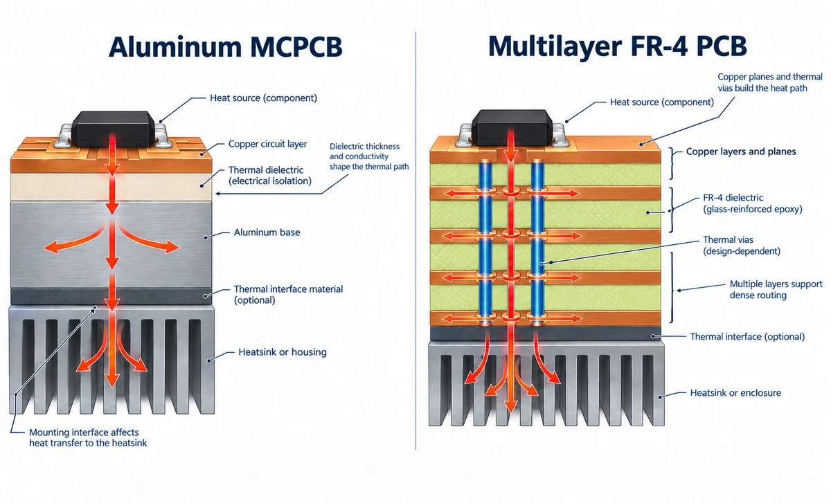
On an aluminum PCB, that path is shaped by:
- the thickness and thermal conductivity of the insulating dielectric,
- the copper layout under the heat source,
- the contact between the aluminum base and the heatsink or housing, including any thermal interface material.
On FR-4, the laminate itself conducts heat poorly through its thickness, so performance depends on:
- copper planes and pours,
- thermal vias under the component,
- the component package,
- the external heatsink or enclosure.
How to read the numbers. JetH PCB's published aluminum PCB reference lists a thermal conductivity of 1.0–2.0 W/m·K as the standard range and 3.0 W/m·K as an advanced reference. These values describe the insulating dielectric layer. They are not the conductivity of the aluminum base or of the finished board, and they are listed by parameter, not as one guaranteed combination on a single board. Confirm the actual material and stack-up for your project.
Do not divide one number by another. The aluminum base, the insulating dielectric and the FR-4 laminate sit at different points in different heat paths, so their published conductivity values should not be compared as a direct ratio to predict component temperature. FR-4 conductivity also differs between the through-plane and in-plane directions, and published values depend on the laminate and the test basis.
Check the basis of the rating. Some suppliers publish a higher "product" conductivity next to a lower "dielectric" conductivity for the same material. One Thermal Clad HT example shows why the basis matters: the Bergquist Thermal Clad selection guide lists 4.1 W/m·K for product thermal conductivity and 2.2 W/m·K for dielectric thermal conductivity for HT-04503, and the two values come from different test methods, so they are not equivalent material properties. Compare like with like: use dielectric conductivity values reported on the same test basis. Where available, also compare area-normalized thermal resistance (for example, °C·cm²/W), with the dielectric thickness and test method stated. A thicker dielectric raises thermal resistance, so a higher conductivity rating does not guarantee a lower junction temperature.
For selection, start from the heat each component dissipates, its allowed temperature and the thermal path, then confirm with thermal analysis or measurement.
When Should You Choose Aluminum PCB or FR-4?
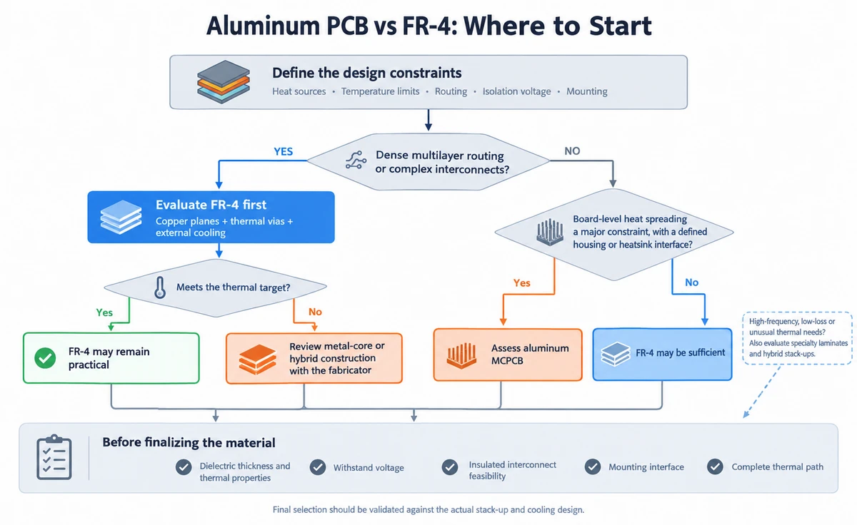
Decide from your design conditions, not from the industry you sell into. The lists below turn the comparison into a set of tests you can check against your own board.
Choose Aluminum PCB When
- A concentrated heat source has a tight temperature limit, and spreading heat across the board is a real design constraint.
- Your circuit fits on a single side or a limited number of layers.
- The board can mount to a housing, lamp base or heatsink through a designed thermal interface.
- The dielectric meets both your thermal needs and your withstand-voltage requirement.
LED boards and some power electronics most often meet these conditions. If your project is LED lighting, see our guide to aluminum PCB selection for LED lighting for the junction-temperature side of the decision.
Choose FR-4 When
- The design needs four, six or more routing layers, or dense signal and power interconnects.
- Copper planes, thermal vias and an external heatsink can meet the thermal target.
- Fabrication flexibility, routing freedom and overall cost matter more than board-level heat spreading.
FR-4 is not automatically unsuitable for thermally demanding designs. Copper planes and well-designed thermal vias can provide a path to an external cooling structure, but the result depends on the component package, via geometry, copper layout, board thickness and mounting interface. Evaluate the complete thermal design against the component temperature limits rather than applying a universal wattage threshold.
When a design needs both multilayer routing and significant heat spreading, evaluate the complete FR-4 thermal path before changing substrates. If copper planes, thermal vias and an external heatsink meet the component temperature limits, FR-4 may remain the more practical choice. If they do not, ask the fabricator to review a metal-core or hybrid construction before routing is finalized, including its insulated interconnects, stack-up feasibility and mounting interface.
When Neither Is an Automatic Choice
For high-frequency, low-loss or unusual thermal requirements, FR-4 and aluminum do not cover every option. Evaluate specialty high-frequency laminates, hybrid stack-ups (such as RF materials combined with FR-4) or other base materials, and have the stack-up reviewed before you commit.
What to Confirm Before Selecting the PCB Substrate
Settle these points before you freeze the material. They also give a manufacturer what it needs to review your design and quote accurately.
- Heat: the main heat sources, the power each dissipates, and each component's allowed temperature.
- Circuit: required layer count, routing density, hole structure and how layers must connect electrically.
- Copper and dielectric: copper thickness, dielectric thickness and thermal conductivity (for aluminum), and the withstand-voltage test conditions.
- Mechanical and thermal interface: board thickness, outline, mounting position, heatsink contact surface, and any thermal interface material.
- Order: prototype quantity, expected volume later, and any manufacturing limits that a special structure introduces.
Send Gerber and drill files, the board outline, a proposed stack-up and a note of the result the board must achieve. If the material or stack-up is still open, describe the target (temperature limit, isolation voltage, mounting) rather than assigning a material number you have not verified. Our engineers can then review manufacturability before production release.
Frequently Asked Questions
Is an aluminum PCB always better for heat dissipation?
No. The aluminum base gives heat a good path to spread, but final performance depends on the whole path: the dielectric layer, the base, and the contact with the heatsink or housing. A poorly mounted aluminum board can run hotter than a well-designed FR-4 board with copper planes, thermal vias and a heatsink.
Can FR-4 be used for high-power electronics?
Yes. Whether it works depends on the component package, thermal vias, copper planes, heatsink and operating conditions. No single power figure decides the material, so evaluate each design with thermal analysis or measurement.
Can an aluminum PCB support multilayer routing and plated through-holes?
Yes, but the available constructions are more limited than those for conventional FR-4. JetH PCB lists 2-layer metal-core boards for production and up to 6 layers for samples, subject to design review. Double-sided boards with insulated plated through-holes are also possible, but each plated barrel must remain electrically isolated from the conductive aluminum base. Feasibility depends on the stack-up, hole structure and insulation scheme, so have the design reviewed before layout is finalized.